Feasibility of multiple micro-particle trapping—A simulation study

1Citations
Citations of this article
16Readers
Mendeley users who have this article in their library.

Abstract

Both optical tweezers and acoustic tweezers have been demonstrated for trapping small particles in diverse biomedical applications. Compared to the optical tweezers, acoustic tweezers have deeper penetration, lower intensity, and are more useful in light opaque media. These advantages enable the potential utility of acoustic tweezers in biological science. Since the first demonstration of acoustic tweezers, various applications have required the trapping of not only one, but more particles simultaneously in both the axial and lateral direction. In this research, a method is proposed to create multiple trapping patterns, to prove the feasibility of trapping micro-particles. It has potential ability to electronically control the location and movement of the particles in real-time. A multiple-focus acoustic field can be generated by controlling the excitation of the transducer elements. The pressure and intensity of the field are obtained by modeling phased array transducer. Moreover, scattering force and gradient force at various positions are also evaluated to analyze their relative components to the effect of the acoustic tweezers. Besides, the axial and lateral radiation force and the trapping trajectory are computed based on ray acoustic approach. The results obtained demonstrate that the acoustic tweezers are capable of multiple trapping in both the axial and lateral directions.

Figures

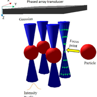
  • Figure 1. Schematic of the multiple trapping acoustic tweezers. The blue hyperbolic space shows the Gaussian beams generated by a phased array transducer (gray plane). The orange line is the intensity profile of Gaussian beam. The red ball is the objective particle to be trapped by the focal points in the center of beams. Green arrows denote wave propagation direction in Gaussian beam.
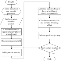
  • Figure 2. Flow chart for creating the multiple-focus acoustic field and calculating the radiation force.
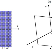
  • Figure 3. Configuration and geometry for the phased array sensor (a) Phased array sensor with 25 × 25 elements; (b) Coordinate system for the calculation of the acoustic field.
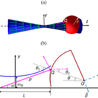
  • Figure 4. (a) An overall view of a single beam acoustic tweezers. Blue hyperbolic space represents the focused acoustic beam. Green vectors denote the wave propagation direction. Pink arrow is an individual incident ray hit on the target particle. Red ball is the target particle; (b) 2D zooming geometry for the analysis of the radiation force when a sphere located at the arbitrary location. Blue line represents the acoustic beam. The incident ray assumed from point with angle α to the beam axis z hits the spherical particle (red line) at point Q. The absolute distance between and is , which is also the radius of the spherical wave front. L is the axial distance between and . and z axis has angle to each other. and indicate the incident angle and refractive angle at the interacting point respectively. ̂ and are the unit vectors representing the directions of the scattering and the gradient forces. Beam waist size is .
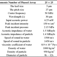
  • Table 1. Simulation parameters.
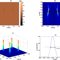
  • Figure 5. Acoustic intensity field for four focus points. (a) Instantaneous pressure field along the beam axis; (b) Acoustic intensity field along the beam axis; (c) Acoustic intensity field across the z-axis; (d) Intensity profile for one of the four focal points across the beam axis and passing through the focal point.
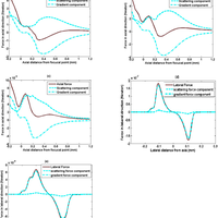
  • Figure 6. Acoustic radiation force along and across the beam propagation direction. The diameter of the particle is 240 μm in coordinate system zoy. (a) Axial radiation force as the particle location varies from (−0.2, 0) to (1.2, 0) mm; (b) Axial radiation force as the particle location varies from (−0.2, 0.02) to (1.2, 0.02) mm; (c) Axial radiation force as the particle location varies from (−0.2, 0.05) to (1.2, 0.05) mm;(d) Lateral radiation force as the particle location varies from (0.13, −0.3) to (0.13, 0.35) mm; (e) Lateral radiation force as the particle location varies from (0.23, −0.3) to (0.23, 0.35) mm.
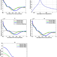
  • Figure 7. Radiation force and displacement trajectory along axial direction. (a) Axial radiation force as the particles travelled along axial direction or z-axis; (b) Streaming velocity along the axial direction; (c) Acoustic streaming velocity combined with radiation force; (d) Integrated force consisted with drag force and radiation force; (e) The plot of displacement trajectories along z-axis.

References Powered by Scopus

Observation of a single-beam gradient force optical trap for dielectric particles

6544Citations
N/AReaders
Get full text

A revolution in optical manipulation

4774Citations
N/AReaders
Get full text

Forces of a single-beam gradient laser trap on a dielectric sphere in the ray optics regime

1562Citations
N/AReaders
Get full text

Cited by Powered by Scopus

Optical tweezer system with no fluorescent confocal microscope for trapping colloidal nanoparticles

0Citations
N/AReaders
Get full text

Register to see more suggestions

Mendeley helps you to discover research relevant for your work.

Already have an account?

Cite

CITATION STYLE

APA

Yu, Y., Qiu, W., Chiu, B., & Sun, L. (2015). Feasibility of multiple micro-particle trapping—A simulation study. Sensors (Switzerland), 15(3), 4958–4974. https://doi.org/10.3390/s150304958

Readers over time

‘15‘16‘17‘18‘19‘20‘21‘2402468

Readers' Seniority

Tooltip

PhD / Post grad / Masters / Doc 9

69%

Professor / Associate Prof. 3

23%

Researcher 1

8%

Readers' Discipline

Tooltip

Engineering 7

64%

Physics and Astronomy 2

18%

Materials Science 1

9%

Computer Science 1

9%

Save time finding and organizing research with Mendeley

Sign up for free
0